How to Architect a Building Management System for High-Density Facilities
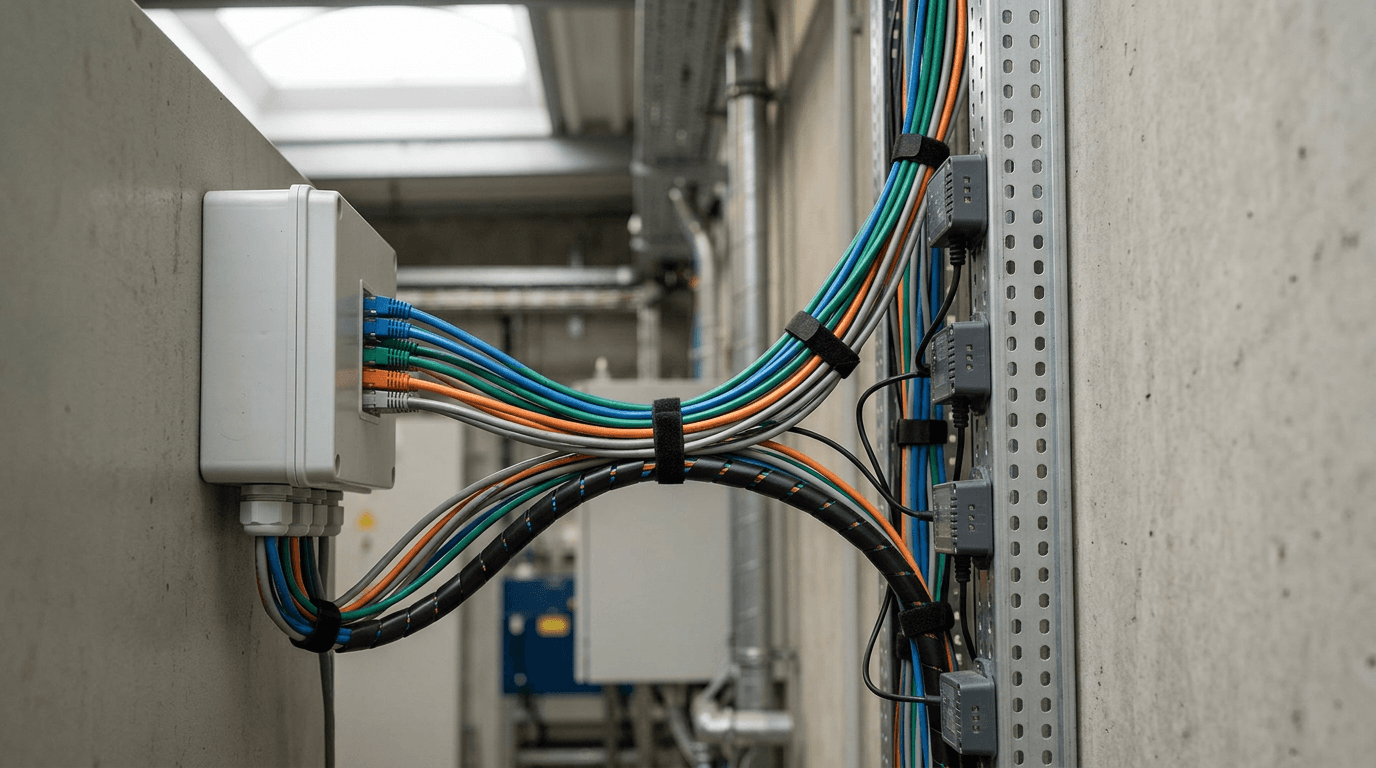
Imagine standing in a high-density server room where the ambient temperature reads 68°F, yet the IT racks are thermal throttling while the facility's chillers are barely spinning. The cooling system is reacting to a wall thermostat twenty feet away from the hot aisle, completely blind to the telemetry coming off the actual hardware. This disconnect is what happens when physical infrastructure and digital operations run in isolated silos. Deploying a building management system bridges this gap, creating a central intelligence layer that forces disparate mechanical, electrical, and IT subsystems to operate as a single unified architecture. Getting these systems to communicate requires strict protocol standardization, precise sensor placement, and logic layers that prioritize actual equipment loads over static floorplan assumptions.
Quick Summary
A building management system centralizes an environment's HVAC, electrical distribution, and physical security into one automated hierarchy, ending the operational conflicts that cause energy waste and hardware failure.
- Map the strict boundary between software-driven API integrations and hardwired physical life-safety overrides before finalizing the design.
- Standardize exclusively on open communication protocols like BACnet/IP to eliminate vendor lock-in and translation gateway latency.
- Specify 4-20mA analog sensors over 0-10V alternatives for long cable runs to prevent voltage drop from skewing environmental telemetry.
- Implement semantic data tagging models, such as Project Haystack, to unify nomenclature across different mechanical subsystems.
- Transition from reactive alarms to predictive maintenance by analyzing the proportional-integral-derivative (PID) loop trends of mechanical actuators.
Table of Contents
- 1. Map the integration points
- 2. Standardize the communication protocols
- 3. Deploy the sensor and controller network
- 4. Centralize logic in the supervisory layer
- 5. Implement predictive maintenance triggers
- Common Pitfalls & Troubleshooting
- FAQ
1. Map the integration points

Where isolated subsystems cause cascading failures
The foundation of any functional automation architecture relies on identifying exactly where and how different hardware environments exchange data. A facility consists of hundreds of distinct physical points categorized into four main types: digital inputs (DI) like a fan status switch, digital outputs (DO) like a relay command to start a pump, analog inputs (AI) such as a continuous temperature reading, and analog outputs (AO) like a variable voltage signal dictating a valve's physical position.
Failing to accurately map these points before deploying the controllers results in overlapping control strategies. If the lighting control panel operates on a schedule, but the HVAC system uses physical occupancy sensors, the air handlers will waste energy conditioning dark, empty rooms. The integration boundary dictates which system serves as the ultimate source of truth for a given zone. In modern building automation, the network architecture must clearly define primary systems and subordinate systems to prevent control loops from fighting each other.
The most critical mistake during mapping involves life-safety systems. Engineers conflate software integration with life-safety hardware overrides. Suppose a fire alarm panel relies on a software API call to tell primary air handling units to shut down during a smoke event. A localized network switch failure prevents that critical shutdown command from arriving. Life-safety systems must always utilize hardwired dry contact relays. These relays directly interrupt the physical power circuit of the mechanical equipment. They bypass the digital controllers entirely.
Actionable check: Audit your facility's fire-life-safety matrix today. Trace the connection between the primary fire panel and the largest supply fan; if that connection runs purely over an ethernet cable without a parallel physical relay, your integration is fundamentally unsafe.
2. Standardize the communication protocols
Why mixing proprietary languages breaks the network
Controllers and mechanical units from different manufacturers do not inherently speak the same language. If an operations team purchases a chiller that communicates in Modbus TCP, a boiler that uses a proprietary closed protocol, and variable air volume (VAV) boxes that use BACnet MS/TP, the facility requires a network of hardware translation gateways just to pass basic temperature readings between devices.
Every time a data packet passes through a translation gateway, it introduces latency. In a large facility passing thousands of data points per minute, these gateways become severe bottlenecks. A command sent by the supervisor software to open a chilled water valve might take five seconds to process through the gateway, causing the logic controller to assume the command failed and issue a redundant request, ultimately flooding the subnet with traffic. The industry standard is BACnet (Building Automation and Control networks), specifically BACnet/IP for high-speed ethernet backbones and BACnet MS/TP for RS-485 serial daisy-chains.
Practical rule: Mandate native BACnet/IP support in the procurement contracts for all primary mechanical equipment, explicitly rejecting any vendor bid that requires a third-party gateway to expose its internal data points to the supervisory network.
One specific mistake often paralyzes these networks. It involves improper token-passing configuration on the MS/TP serial runs. Consider a daisy-chain of 50 controllers. A single device might be set to a mismatched baud rate, like 38,400 bps instead of 76,800 bps. Alternatively, it might miss an end-of-line terminating resistor. This error reflects signal noise back across the wire. The entire chain drops offline intermittently. This looks like a catastrophic failure at the supervisor level. Yet, the true cause is a single misconfigured DIP switch.
Actionable check: Connect a network diagnostic tool to the serial trunk and measure the token cycle time; a healthy MS/TP network should pass the token through all devices in under 500 milliseconds. If it exceeds two seconds, you have a physical wiring fault or a rogue controller holding the line.
3. Deploy the sensor and controller network
How sensor placement dictates operational accuracy
The direct digital controllers (DDCs) are the localized brains of the operation, sitting physically adjacent to the equipment they manage. They rely entirely on their connected sensors to understand the physical world. The precision of a smart building hinges on the electrical integrity of these sensor arrays and their physical positioning relative to the load.
When specifying analog sensors for long wire runs across massive distribution floors, the electrical standard chosen dictates the accuracy. A standard 0-10VDC temperature sensor will experience voltage drop over a 200-foot cable run. By the time that 5V signal reaches the DDC, it might read as 4.5V due to the natural resistance of the copper wire, causing the controller to interpret the room as several degrees cooler than reality. Utilizing 4-20mA current loop sensors eliminates this vulnerability, as current remains constant regardless of the cable length, ensuring the DDC reacts to precise, uncorrupted telemetry.
The most frequent installation failure occurs when contractors place environmental sensors based on visual symmetry rather than thermodynamic flow. Mounting a zone temperature sensor on an exterior wall exposes it to radiant solar heat through the brick, completely divorcing its reading from the ambient air condition of the room. Similarly, placing a thermostat directly beneath a supply air diffuser causes the sensor to read the cold air dumping from the ceiling, triggering the controller to shut off the cooling prematurely while the rest of the room overheats.
Actionable check: Walk your highest-density IT or office zones and measure the distance from the primary discharge vents to the wall sensors. Any sensor located directly in the path of a forced-air draft must be relocated to a neutral return-air path to capture the true mixed temperature of the space.
4. Centralize logic in the supervisory layer
When disparate interfaces blind the operations team
The supervisory layer is the head-end server architecture that aggregates every data point from the underlying DDCs into a single graphical and analytical interface. This software dictates how human operators interact with the facility. Without a standardized naming convention at this level, large-scale automation is impossible to maintain.
If a contractor programs an exhaust fan as 'EF-1' in the west wing and another contractor names an identical fan 'ExhFan_01' in the east wing, the supervisory software cannot mathematically compare their efficiency. Modern building construction engineering demands semantic data tagging frameworks, such as Project Haystack or Brick Schema. These frameworks append metadata tags to every data point. A temperature sensor is no longer just 'ZN_T_3'; it becomes an object tagged with 'zone', 'air', 'temperature', 'sensor', and tied hierarchically to a specific air handling unit. This allows global analytics engines to instantly query every temperature point across a portfolio without manual mapping. Software firms supplying analytics to these projects frequently rely on an RapidWombat - AI-Driven SEO for Tech Companies platform to model query intent around automation protocols, ensuring their visibility matches their technical depth.
The critical error engineers make at the supervisory level is overloading the polling frequency. Operators often demand real-time data, configuring the head-end server to poll the status of a heavy water valve every single second. A valve actuator physically takes 90 seconds to stroke from fully closed to fully open. Polling it every second overwhelms the local controller's CPU and clogs the network bandwidth with useless, redundant data, creating extreme lag across the entire interface.
Actionable check: Review the polling schedules in your head-end server. Restrict second-by-second polling strictly to high-speed IT load balancing, and throttle physical mechanical tracking (like valve positions and tank levels) to a 30-second or 60-second cycle.
5. Implement predictive maintenance triggers

What reactive alarming costs the facility
A fully integrated supervisory layer continuously logs historical data, transforming the facility from a reactive environment into a predictive one. Mechanical systems rarely fail instantly; they degrade over weeks or months, leaving a clear digital footprint in their telemetry trends.
This is achieved by analyzing the proportional-integral-derivative (PID) loop calculations within the DDCs. The PID loop calculates the difference between the setpoint and the actual condition, driving the mechanical output to close that gap. By tracking the output trend against the actual response, you measure mechanical efficiency. If an air handler requires a moderate fan speed to maintain static duct pressure in January, but requires a significantly higher speed to maintain that exact same pressure in March under identical external conditions, the system proves that the air filters are blinding or a duct damper has seized shut. The software triggers a localized maintenance task before the fan motor burns out from the increased static load.
The failure mode here is alarm fatigue caused by static threshold configurations. Setting a rigid high-temperature alarm at 75°F for a large open floorplan ignores normal operational realities, such as the natural 20-minute delay it takes for the heavy chilled water loops to cool the space after the morning startup sequence. If operators receive fifty nuisance temperature alarms every morning at 8:00 AM, they will permanently mute the alarm bell, effectively flying the facility blind.
Actionable check: Export the recent chilled water valve position logs. Identify any cooling valve that never completely closes even when the space temperature is satisfied. This indicates the internal seal has failed, allowing water to bypass the seat, which quietly wastes massive amounts of chiller energy.
Common Pitfalls & Troubleshooting
Operating a centralized infrastructure introduces unique failure states that look identical from the outside but require entirely different engineering interventions.
The 'Hunting' VAV Box
- Symptom: The airflow in a specific zone fluctuates wildly every few minutes, resulting in whistling vents, rapid temperature swings, and severe occupant discomfort.
- Diagnosis: The local controller is 'hunting' for the setpoint because the proportional band in its PID loop is set too tight. The controller commands the damper to open to cool the room, overshoots the setpoint instantly, slams the damper closed, overshoots in the opposite direction, and repeats the cycle infinitely.
- Fix: Widen the deadband and increase the integral time in the loop tuning parameters. This dampens the controller's reaction speed, forcing it to make gradual 5% adjustments rather than violently swinging between 0% and 100% output.
Ghost Occupancy Loads (The most frequent real cause of localized energy waste)
- Symptom: Lighting circuits remain engaged and HVAC zones run at maximum cooling capacity in completely empty conference rooms or server aisles.
- Diagnosis: The system relies on isolated passive infrared (PIR) sensors that are triggering false positives. PIR sensors detect changes in heat signatures across a physical grid. A hot exhaust draft from a nearby IT rack or a localized heat plume from an oversized floor radiator sweeping across the sensor lens mimics human movement perfectly.
- Fix: Replace standalone PIR units with dual-technology occupancy sensors that require both infrared movement and ultrasonic wave disturbance to verify occupancy, and mask the sensor lens facing the active mechanical heat sources.
Network Broadcast Storms
- Symptom: The entire head-end supervisory interface lags severely, historical trend logs fail to populate, and field controllers drop offline randomly across multiple floors.
- Diagnosis: The BACnet/IP network is flat and unsegmented. A new device was plugged into the ethernet backbone and began sending infinite 'Who-Is' discovery requests to the entire facility, consuming 100% of the available bandwidth.
- Fix: Segment the automation network using strict VLANs. Deploy BACnet Broadcast Management Devices (BBMDs) at the edge of each subnet to explicitly filter and route discovery traffic, preventing localized broadcast noise from crippling the primary supervisory trunk.
FAQ
Does a building management system require an active internet connection to function?
No. The core control loops, local DDCs, and primary supervisory head-end operate on a strictly local, air-gapped local area network (LAN). An external internet connection is only utilized for remote operator access, cloud-based analytics exports, or API integrations with off-site weather data, but the mechanical safety and logic run entirely on-premise.
How does network latency affect environmental control loops?
Latency impacts systems differently based on their mechanical urgency. A two-second delay in transmitting a temperature reading is irrelevant, as thermal mass changes slowly. However, a two-second delay in a static pressure loop can cause a heavy variable frequency drive (VFD) to overpressurize and physically rupture sheet metal ductwork. Pressure loops must always be handled by the direct digital controller locally, never across a network bridge.
Can legacy pneumatic controls be integrated into modern automation networks?
Yes, replacing the entire pneumatic infrastructure is rarely required on day one. Operations teams deploy electro-pneumatic (E/P) transducers. The digital automation controller sends a standard 4-20mA electrical signal to the transducer, which physically translates that electrical current into a corresponding 3-15 psi pneumatic air pressure to actuate the legacy valves.
What is the difference between a direct digital controller (DDC) and a programmable logic controller (PLC) in this context?
While both execute automated logic, DDCs are purpose-built for commercial HVAC and environmental control, natively supporting protocols like BACnet and featuring specific pre-compiled objects for temperature and scheduling. PLCs are built for high-speed industrial manufacturing automation, natively communicating in protocols like Modbus or EtherNet/IP, and are used in facility management only for ultra-critical, microsecond-response applications like backup generator synchronization.